Acrobat Printable Version
|
BODY-03, Sunroof Operation, Troubleshooting, and Repair
|
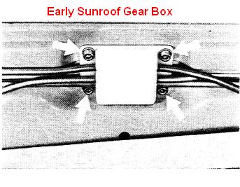
 The sunroofs on 944s are raised and lowered by two lifting arms at the rear edge of the roof. On cars made after February 1986, the lifting arms are operated by plastic gears (one for each lifting arm mechanism). The plastic gears have a small set of teeth which operate the lifting arms. They also have a large set of teeth which are driven by a flexible cable. The cable is driven by the sunroof motor. For cars produced before February 1986, there is a gear box between the two lifting arm mechanisms. This gear box has a single gear which moves the lifting arms via two short lengths of drive cable. The guide tubes for the short sections of the flexible drive cable are routed such that the drive cables are directly engaged in the teeth on the lifting arms as opposed to using a plastic drive gear in each lifting arm housing. The sunroof drive motor assembly is located in the rear hatch area behind the vertical section of carpet on the driver's side of the car. On most cars the motor assembly will have a plastic cover over it which is held in place by six Phillips head screws. The sunroof system on all 944s uses a series of micro-switches to stop the lifting arms in different positions. The functioning of the sunroof depends on the ignition switch position and the direction that the console switch is operated. The ignition switch on 1985.5 and newer cars is a three-position switch whereas the early ignition switch is a two-position switch (OFF-ON). On the later cars, it's a OFF (0) - ACCESSORY (1) - ON (2) switch. You'll frequently hear the ignition switch "ON" position referred to as ignition switch position 2. To operate the sunroof in the open or closed direction, the ignition switch is turned to the "ON" position. To release the sunroof the ignition switch must be in the "OFF" position for the early 944s or in the "ACCESSORY" position for the late model 944s. Specifics on how to operate and remove the sunroof are discussed in another section of this procedure.
All sunroofs installed since February 1986 have three limit switches which are operated by a plastic cam attached to the sunroof drive cable. The cam assembly rotates as the drive motor moves the drive cable and as the cam rotates it operates the limit switches. In cam position 1, the lifting arms are fully retracted back against the body of the sunroof so that the sunroof can be removed from the car. This is referred to as the "released" position. In this particular instance, both Limit Switches I and II are made. Limit Switches I and II are ganged together and can only be adjusted together. Limit Switch I is the bottom switch and Limit Switch II is the top switch. They function to stop the lifting arms in the "locked" position. If the lifting arms are in the released position and both limit switches are not made or are not functioning properly, the lifting arms can not be moved to the "locked" position. In cam position 2, the lifting arms are partially raised so that the sunroof is still closed but, it is locked in the closed position. As the lifting arms are moved toward the locked position, the cam rotates. When the cam reaches position 2, Limit Switch II drops out to stop the sunroof motor. As previously mentioned, the ignition switch must be in the ACCESSORY position to operate the sunroof between the retracted and locked positions (from cam position 1 to 2). When moving the lifting arm from the locked position to the released position, movement of the lifting arms is stopped by the slip clutch on the sunroof motor when the lifting arm tabs contact the body of the sunroof opening. This is a very common problem area. Over time, the motor slip clutch torque tends to increase. There really isn't a good explanation for why this occurs but, it does. Eventually, the torque will get high enough so that when the lifting arms are retracted and come in contact with the body, the sunroof motor have enough torque to cause the drive cable to strip the teeth on the plastic sunroof gears. The procedure for adjusting the slip clutch torque will be discussed later. To raise the sunroof from the locked position, the ignition switch must be in the ON position. When the console switch is depressed (Up Arrow), the sunroof will start to raise and the cam rotates. As soon as the cam starts to rotate, Limit Switch I drops out. The sunroof will continue to raise as long as the console switch is depressed until the roof reaches the fully open position (cam position 3). When the cam hits limit switch III, the sunroof stops in the fully open position. To lower the sunroof from the fully raised position, the ignition switch must be in the ON position. When the console switch is depressed (Down Arrow), the sunroof lowers until cam position 2 is reached. When the cam makes Limit Switch I, the sunroof stops in the locked postion. The operation of sunroofs on 944s produced from 1982 to February 1986 is essentially identical to that of later 944 sunroof systems. The primary differences are in the physical construction of the sunroof equipment.
One of the major differences is the set up of the drive motor and limit switches. The early sunroof assembly does not use a rotating cam to operate the limit switches. Instead, there is a guide rail attached to the sunroof motor which extends toward the rear of the car. At the very back of the guide rail is two limit switches. These are equivalent to Limit Switches I and II on the late model sunroof systems. They function together to stop the lifting arms in the locked position and are operated by a plastic dog that is attached to the end of the drive cable. Like the late model sunroof, in the locked position, one limit switch is made and one is not. To open the sunroof, the ignition switch must be in the ON position. When the console switch is depressed the sunroof moves in the open direction and is stopped when the mirco-switch mounted between the sunvisors drops out. The micro-switch is operated by a tab attached to the front edge of the sunroof hatch. As the back of the sunroof hatch raises during opening, the tab on the front of the hatch swings down. When it swings down far enough, the mirco-switch drops out (electrically opens) and the sunroof motor stops. This micro-switch is also used on the late model sunroofs but, merely functions as a backup to Limit Switch III.
From the locked position, to move the lifting arms to the released position (for sunroof removal), the ignition switch must be in the OFF position. As the lifting arms move to the released position, movement of the lifting arms is stopped by the motor's slip clutch when the lifting arm tabs contact the body of the sunroof opening. And, when moving the lifting arms from the released position to the locked position, the sunroof motor is stopped when one of the limit switches drops out. The mircro-switch between the sunvisors also performs an additional function on both early and late model sunroofs. It tells the system that the sunroof is installed. If the sunroof is installed but, the lifting arms are released, the system will automatically move the lifting arms to the locked position when the car starts moving. If the sunroof fails electrically, it can be operated manually. However, operating an early sunroof manually is difficult at best and should only be done if absolutely necessary. Directions for sunroof manual operation are contained in another section of this procedure. To troubleshoot problems with the sunroof system, refer to the troubleshooting section of this procedrue. |
Normal Operation
On pre-1985.5 cars, the sunroof is operated by turning the ignition switch to the "ON" position. The sunroof console switch is then pushed back ("A" direction) to open the sunroof and pushed forward ("B" direction) to close.
The ignition switch on 1985.5 and newer cars is a three-position switch whereas the early ignition switch is a two-position switch (OFF-ON). On the later cars, it's a OFF (0) - Accessory (1) - ON (2) switch. You'll frequently hear the ignition switch "ON" position referred to as ignition switch position 2. To operate the late model sunroof, turn the ignition switch to the "ON" position. The sunroof console switch is then pushed back (up arrow) to open the sunroof and pushed forward (down arrow) to close.
Removing the Sunroof
When raising the sunroof lifting arms from the retracted position (for removal), the lifting arms should automatically stop at the locked closed position.
Since the position of the slip clutch adjustment screw has not been altered, it is not necessary to perform a slip clutch adjustment.


Installing the Sunroof


Sunroof Manual Operation


| Sunroof motor will not operate. | Bad Fuse | Early 944s (Up to February 1986)
Fuse 9 - Additional Fuse Panel (Motor) Fuse 8 - Main Fuse Panel (Relay)
Fuse 8 - Relay
|
| Micro-Switch between Sun Visors Limit Switches Main Sunroof Relay Console Switch Directional Relays Sunroof Motor Ignition Switch |
Sunroof Component Testing - ELECT-18 | |
| Lifting arms retract to the "released" position for removal but will not raise to the "locked" position. | Sunroof Console Switch Mirco-Switch between Sun Visors Limit Switch 2 Directional Relay 1 |
Sunroof Component Testing - ELECT-18 |
| Sunroof Arms move up and down but will not retract for removal. | Main Sunroof Relay Console Switch Limit Switch 1 |
Sunroof Component Testing - ELECT-18 |
| Sunroof will raise to the open position but will not lower to the locked position. | Console Switch Limit Switch 1 Directional Relay 2 |
Sunroof Component Testing - ELECT-18 |
| Sunroof lowers but will not raise. | Micro-Switch between Sun Visors Console Switch |
Sunroof Component Testing - ELECT-18 |
| Sunroof automatically raises when car is rolled backwards or forward. | Limit Switch 2 bad or misadjusted. | Sunroof Component Testing - ELECT-18 |
| Sunroof motor turns but nothing happens. | Slip clutch torque set too low. Plastic sunroof gears bad (late sunroof) or sunroof gear box (early sunroof) bad. |
Replace plastic sunroof gears (BODY-04) or replace gear box. |
| Sunroof arms not level or raise unevenly. | Drive cable Plastic sunroof gears |
Replace plastic sunroof gears (BODY-04) or drive cables as necessary. |
Clark's Garage © 1998


