Acrobat Printable Version
|
IGN-02, Speed and Reference Sensors - Information, Checking, Replacement, and Adjustment
|
The 944 Engine Managment system uses two crankshaft sensors. One (Reference Sensor) determines the #1 piston (front of the engine) position relative to Top Dead Center (TDC). When we refer to TDC, we are referring to the pistons highest position on the compression stroke. The second sensor (Speed Senors) counts the teeth on the flywheel and provides this signal in the form of pulses to the Engine Management Computer (DME) for engine speed in RPM (Revolutions Per Minute). Using the combination of the two signals, the DME can determine where the engine position is at any point in its cycle to apply the correct fuel injector cycling and correct ignition firing. The speed sensor's signal is also used as a safety feature by the DME (after initial cranking is complete) to shut down the fuel pump if engine speed falls below 300 RPM.
The speed and reference sensors can be one of the sources of a number of starting and running problems. This procedure will describe how to test the sensors for proper operation. It will also describe how to replace and adjust the sensor clearance if they are bad.
The sensors are located on the top of the clutch housing at the back of the engine. You can locate them by looking from the driver's side of the car (left-hand drive) down at the back of the engine near the firewall. Here's a picture showing what the sensors look like:

Checking Sensor Operation
Sensor Resistance Checks
An operational check of the speed and reference sensor output signals is the ultimate test to show whether the sensors are providing proper signals to the DME computer. However, to correctly perform the test, it requires an oscilloscope. We'll also discuss checking the output with a multimeter.
The sensor output signals can also be checked using a multi-meter. However, checking with a multi-meter will only tell you if there is and output signal and will not correctly measure the magnitude of the output voltage. So, it will not tell you if the signal is of significant magnitude to be sensed by the DME computer.
Another way to check the operation of the speed and reference sensors it to crank the vehicle and watch the response of the tachometer. If the tachometer jumps during cranking, the speed and reference sensors are probably good. If it does not jump, it indicates a problem with the speed and/or reference sensor or the DME computer. If it's the speed and/or reference sensors, it could be a bad sensor or the clearance gap is too large (see "Adjusting Sensor Clearance").

Sensor Installation
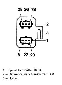
The mounting bracket is labelled as follows:
It is sometimes difficult to read the marks on the mounting bracket. If you can not read the marks, the sensor closest to the firewall is the speed sensor.
I ran across a situation once while installing and engine in a 944 where the wire labels were missing from the wire connectors going to the DME Plug connector and the connectors had been removed from their mounting bracket. So, it was impossible to tell which wiring harness connector went to which sensor. To identify the connectors, I had to take resistance readings using an ohmmeter from the DME Plug connector to the sensor connectors. If you run into the same situation, you can use the diagrams below and an ohmmeter to determine which connector goes to which sensor.


I have a clearance adjustment sensor. This is an old speed sensor with the electrical lead cut off to which I have washer permanently glued.

Clark's Garage © 1998