The following ignition switch replacement procedure was authored by Dean Smith. I'd like to thank Dean for taking the time to write such a complete, detailed procedure. He also took the time to document the replacement with pictures. It will make your ignition switch replacement a breeze.
Foreword by Author
I was having starting problems that were driving me crazy. I
re-soldered the DME, replaced the coil, and checked the speed and reference
sensors. Everything was ok. Finally I located the problem. With the
ignition switch and its associated mounting out of the car, it would start no
problem. As soon as I install it in the car it would not work. Closer
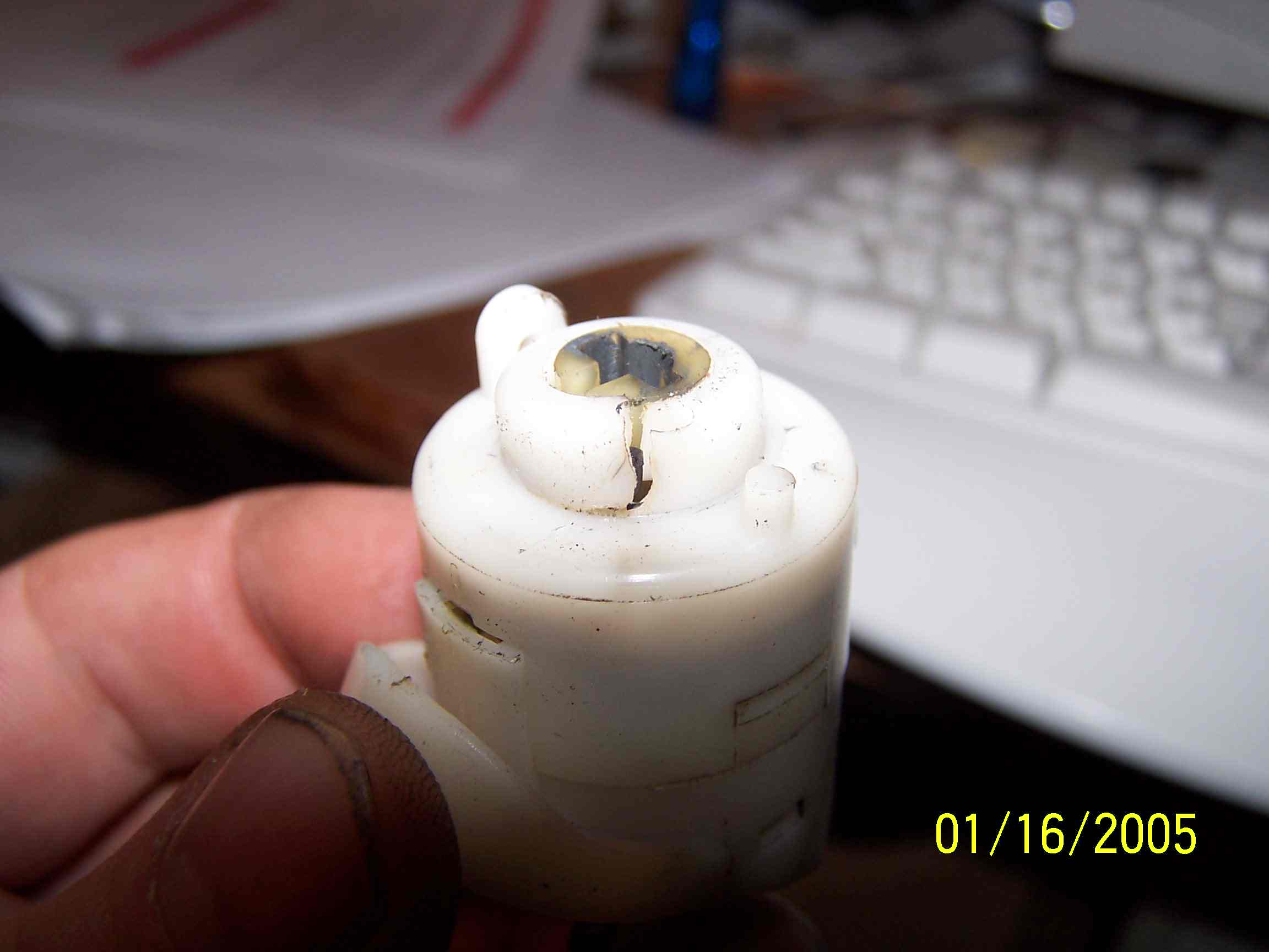
inspection of the switch revealed that it was cracked .
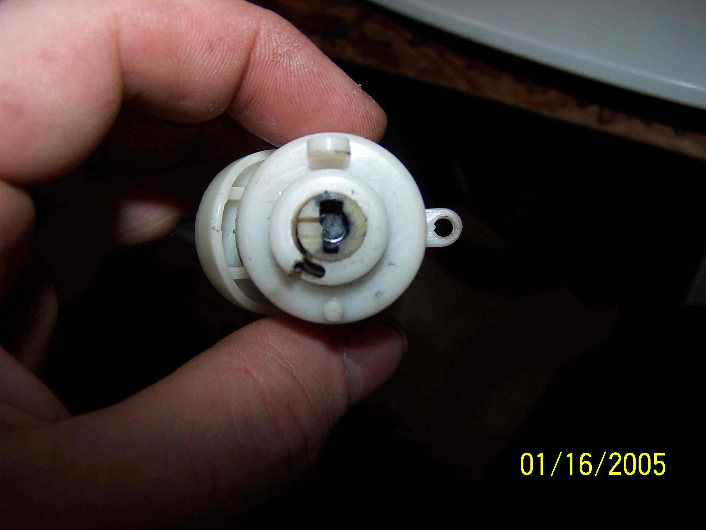
These are a couple of photos of the broken switch.
Crack in the side of Ignition Switch
Looking at front of the Switch
Back of the switch
The following is a basic set of instructions and photos from my 1987 924s.
This car does not have air bags and I have a Dino Wheel so your car may be
different.
Ok lets get started. First off you will be dealing with allot of
little screws. Make sure that you have a container to put them in as you
take things apart. It is also important to lay things out in order as you
remove then as it is easy to leave something out during the reassembly
Dean Smith
Tools that you will need:
Phillips screwdriver #1 Tip (smallest of the standard sizes)
Metric Allen wrench set
Couple of various sized flat screwdrivers
Small pry-bar
Hammer
Brass drft or large deep dish socket
Small scribe or small coal chizzes to mark location of the wheel relative
to the steering column
You may need a Steering wheel puller
Good Shop Light
Lets Get Started
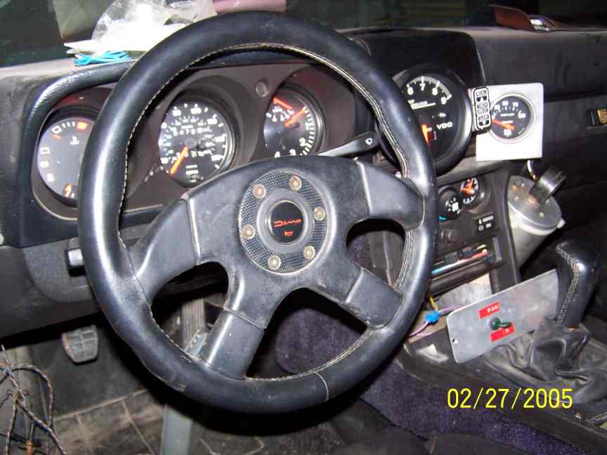
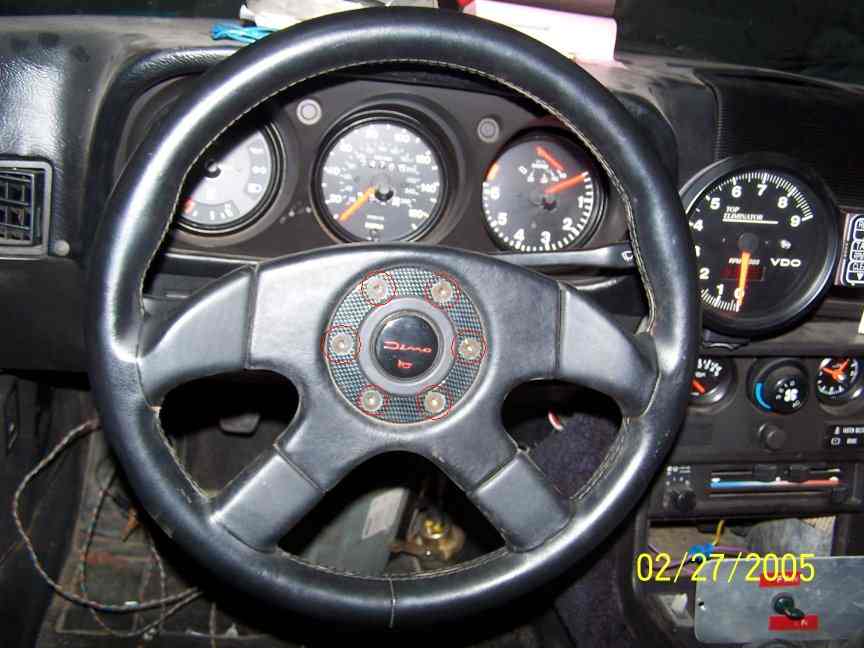
Here is my steering wheel. Note that it is centered and double check that the wheels are strait.
Here is a couple of photos of the left and right sides.
To remove my wheel I have to take the six Allen bolts out in the center of the wheel. THIS IS NOT THE SAME AS A STOCK STEERING
WHEEL. Refer to BODY-25, Steering Wheel Removal and Installation for more information on steering wheel removal.
Once the wheel is free you have to disconnect the wires for the horn. THIS IS NOT THE SAME AS A STOCK STEERING WHEEL
Next remove the rubber boot from around the adaptor/crush zone.THIS
IS NOT THE SAME AS A STOCK STEERING WHEEL
On my set up there is a marking for where the "TOP" should be. If
you have not done it already make sure your wheel is centered. THIS IS NOT THE SAME AS A STOCK STEERING WHEEL
Next remove the center nut. This may requite some muscle Mine comes off rather easy. I put a large screwdriver through the adaptor bracket and
hold it while I take the nut off with a socket. Take the nut and washer of but DON'T TAKE THE ADAPTOR / WHEEL OFF YET. THIS IS NOT
THE SAME AS A STOCK STEERING WHEEL
Once the nut and washer are off you have to scribe the shaft and the adaptor. On the stock wheel you will be scribing the wheel. The mark on the adaptor is hard to see but it is there. Note the mark on the steering column.
Once you mark or index the parts you can continue taking it apart. Slide the steering wheel or steering wheel adapter off of the steering column.
Now you are looking at the top of the switches / stalks. Remove the three flat head screws on top of the stalk.
Now that you have removed the screws the stalks will be loose. You now have to remove the plastic housing around the stalks. It splits
longitudinally and is held in place with two screws that are from below. The reason I did not remove this first is it is easier with the wheel removed and
with the stalks loose it is easier to remove the plastic pieces. Here are a couple of photos showing the screw locations looking up from below.
Here is a photo of the two screws. Note that they are two different sizes.
Now it is time to CAREFULLY slide the stalks off the column. There are a bunch of wires connected to the switches. In my car I don't have to
remove them. I carefully pull them forward from underneath as I gently pull on the switches out. You will also note that the two stalks / switches can
separate from each other. If this happens it is ok. Just carefully continue to pull/guide the wires out until the switch clearers the steering
column. Repeat the process with the second one. If the two switches came apart I then CAREFULLY put the two switches back together once
they are removed. The following photo shows the top switch removed.
This photo shows the bottom switch removed.
Both switches removed and reassembled. Note that I still have the wires attached. You could remove the wires but I prefer to do it this way because if
you forget to hook up a wire that happens to pull back through the dash it will be a real pain to attach it after you put it all back together.
Another photo of the two switches.
This is what you should now have left. Note the three little holes that are where the three screws went that hold the switches. These can be broken off very easily. DO NOT
PRY/LEAN or hang anything from these. If you brake any of these you will have to replace the whole piece. A couple of other things to note ate the
bearings around the column and the Allen head bolt that is visible on the left side of the column.
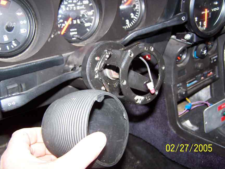
Here is another photo from the side. The next thing to remove is the plastic spacer collar that is around the steering column. To get this off I pry
gently but firmly in the slots around the bottom. Once it moves a little I switch to a small pry bar that is thicker and wider than my largest screwdriver
and carefully work it off. DO NOT PRY ON ANY OF THE THREE SMALL SCREW HOLE'S AS THEY WILL BRAKE OFF.
The piece that my screwdriver is touching is the spacer collar.
The piece removed.
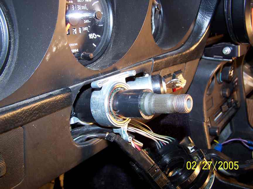
Now you have to remove the Allen head bolt on the left side of the column.
You get at this through a whole in the bottom of the dash.
With this bolt removed the asemble with the ignition switch will slide out. Note that there are a bunch of wires attached to the back of the
switch.
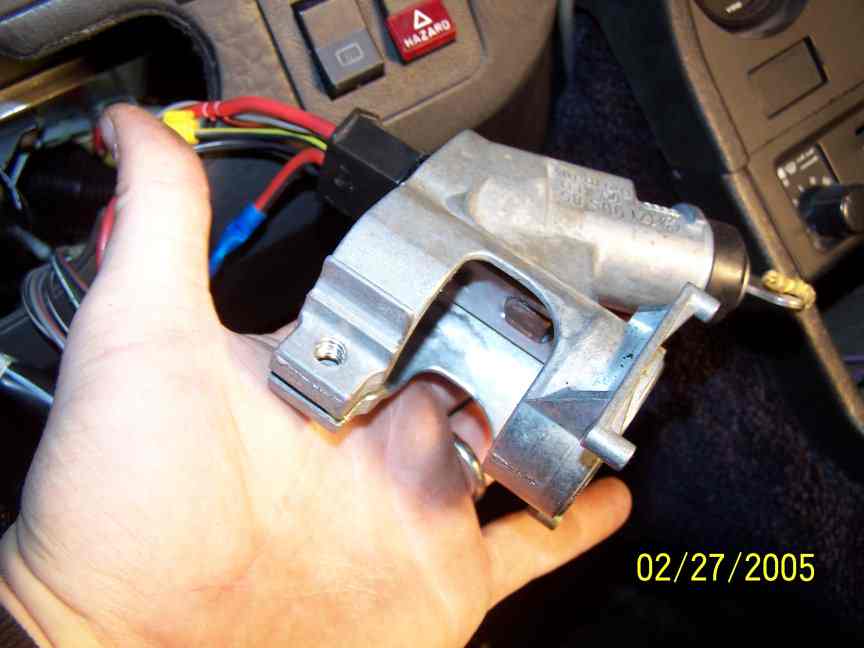
Unplug the wires from the back of the ignition switch. Now flip the piece over and look at the back where the wires were plugged
in and you will see a small Phillips screw. Remove this and the switch will slide out.
Here is the unit with the screw removed.
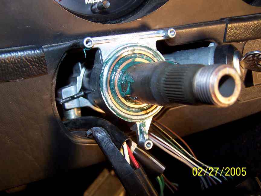
You can then slide the switch out.
On my new switch I put some grease on the end of the switch where the tang from the lock engages as this will see alot of wear.
You are now ready start the reassembly. I will not cover the whole thing just a couple of highlights.
When I put the bracket back I packed the bearings with fresh grease.
The plastic ring/spacer will get some burs on it. I lightly sanded / filed them off before I reinstalled it. I also put a light coating of grease
inside to aid in it slipping back on. When reinstalling this do not use a screwdriver and a hammer to tap it in place. It will damage the plastic or
even split it. I use a large deep socket and tap on it alternating forum side to side.
When I install the plastic trim pieces I again do this with the switches in place but not screwed in place. this will give you a little play when
you put the trim pieces back on. In the following photo you will se how I place the top trim piece. I then push it down and back in place. It
should just snap in place.