ELECT-22, Air Flow Meter (AFM) Operation and Testing
Acrobat Printable Version
Introduction
The following article provides a summary of the operation of the 944 Air Flow Meter (AFM), also commonly referred to as the Air Flow Sensor. Also, covered is a procedure for testing the AFM and correcting problems related to erratic operation.
If you'd like more detailed information about the operation of the AFM, FR Wilk has written a very comprehensive article on the AFM. The article is located at http://www.the944.com. What I've provided below is simply a summary of that article.
Operation
There are two different Air Flow Meters used on 944s although externally they are similar in appearance. Both AFMs use a flapper or barn door arrangement where, as air flow through the meter increases, it forces the barn door further open. The movement of the barn door moves a wiper arm across the conducting strip of a variable potentiometer. The sensor has a voltage applied to it which is supplied by the DME computer. As the barn door opens and the wiper arm moves across the variable potentiometer, the output voltage from the AFM increases. This output signal is sent back to the DME to be used as an air flow signal.
The primary differences between the early 944 AFM (pre-1985.5) and the late AFM is that the input voltage from the DME computer is different and the type of output signal from the AFM back to the DME computer is different. In both AFMs, the DME uses a ratio of the supply voltage (from the DME) to output voltage (from the AFM) for air flow signal development . The early AFM receives an unregulated 12 VDC supply from the DME. The voltage output from AFM is not proportional to the change in barn door position but instead increases exponentially as the barn door is opened. The output signal is however, proportional to the increase in air flow. Consequently, what the DME receives from the meter is in effect an actual air flow signal. On the later AFMs, the input voltage from the DME is a regulated 5 VDC supply. The output signal from the AFM is a voltage that increases linearly as the barn door opened. What this does is to simplify the construction of the later AFM. However, it now requires the DME to interpolate the input signal from the AFM to obtain an air flow signal.
The main problem that occurs with the AFMs over time is that the wiper arm contacts wear grooves in the conducting strip of the variable potentiometer. When that happens it can lead to erratic voltage output from the AFM which will cause the car to hesitate or stumble as you accelerate. In the picture below you can see the potentiometer conducting strip and the grooves in the strip. In the AFM shown the grooves in the strip are not yet bad enough to cause erratic operation of the AFM.
NOTE
The AFM can be tested in the car. However, it is extremely difficult and I prefer to remove the AFM for testing.
Testing the AFM (Installed)
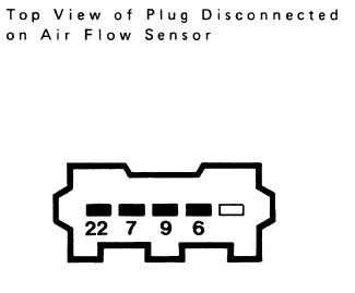
Note: Here's a drawing which which shows the terminal numbers. Realize that you're looking into the end of the wiring harness plug. So, the terminals on the AFM plug will be reversed from the terminals show below from the plug.
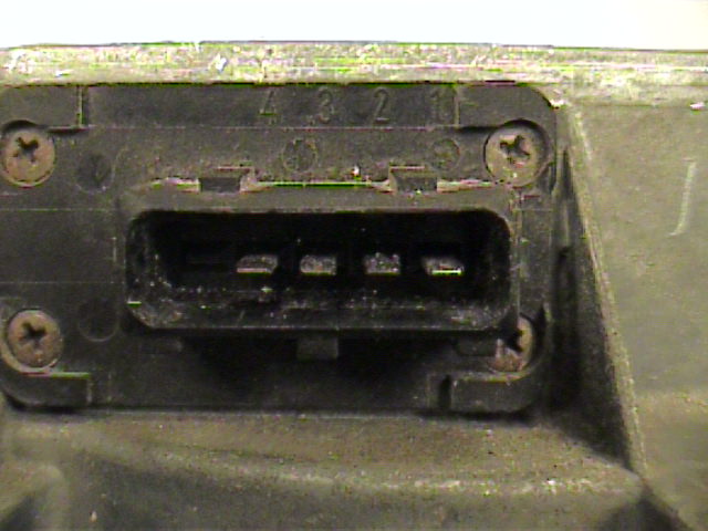
Note: The terminals on the AFM itself are label 1-2-3-4. The terminals on the wiring harness plug correspond as follows:
Plug Terminal
AFM Terminal
Connection
22
1
Air Temperature Sensor
7
2
Output Voltage to DME
9
3
Input Voltage from DME
6
4
Ground
Push back the protection sleeve on the air flow sensor connector. The connector remains attached. Connect a voltmeter to terminals 9 and 6 on the back of the connector. Turn the ignition switch to the ON position. If you have an early 944 (pre-1985.5), the voltmeter will probably read approximately battery voltage (12 VDC). However, it should read a minimum of 8 VDC. If you have a late model 944, the voltmeter should read 5 VDC +/- 0.5. This is the AFM input voltage.
Connect the voltmeter between terminal 7 on the back of the connector and ground. Here you should read 150 - 250 mV.
Slowly push the sensor plate (barn door) to the full open position using a not-to-hard, smooth item inserted through the filter intake opening. The voltage should rise to slightly less than the input voltage measured in Step 1. You are measuring the output voltage in this step. The voltage should rise steadily with not drop in voltage or erratic changes in voltage. If this happens, there are dead spots in the AFM potentiometer conducting strip. You may be able to correct this by bending the AFM wiper arm. This will be discussed later.
Check temperature sensor I (intake air temperature). Turn the ignition switch off and pull off plug on air flow sensor. Connect and ohmmeter between terminals 6 and 22 on air flow sensor (both outer male terminals on the sensor plug). With air temperature between 15 - 30 °C, the ohmmeter should read 1.45 - 3.3 k-ohms. If the air temperature sensor reads open, it will cause a rich mixture. If it reads a short, it will cause a lean mixture.
Test Procedure (AFM Removed)
Tools
Multimeter
Test Leads
9 VDC Battery
9 V Battery Connector
Small Female Spade Connectors (2)
Electrical Tape
Making Up Test Connections
To test the AFM with it removed from the car, you'll need a voltage source. The simplest solution to this is a 9 VDC battery. To make up the leads, I went to Radio Shack and obtained a 9 V battery connector which had leads with bare ends connected to it.
Next, you'll need to crimp a small female spade connector to each of the bare ends. Again, you'll probably have to go to an electronics store and look for the smallest female spade connectors they have. I had small female spade connectors. However, they were actually one size larger than what I needed. So, I had to wrap the spades with electrical tape to keep the from touching when connected to the AFM connector.
Test
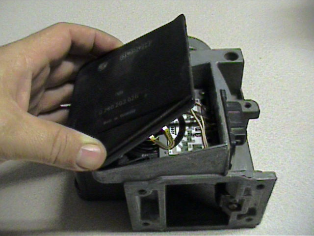
With the AFM removed from the car, remove the cover from the AFM. It will be glued to the body of the AFM by a bead of silicon sealant. You'll have to cut the sealant bead at the bottom edge of the cover where it mates to body of the AFM. You can use a sharp knife or razor blade to cut the sealant.
Here's a look at the inside of the AFM electronics:
1.
Input Voltage Terminal (from DME)
2.
Ground
3.
Temperature Sensor Output
4.
Sensor Output Voltage (to DME)
5.
Potentiometer Wiper Arm
6.
Potentiometer Resistor Board
7.
Potentiometer Conducting Strip
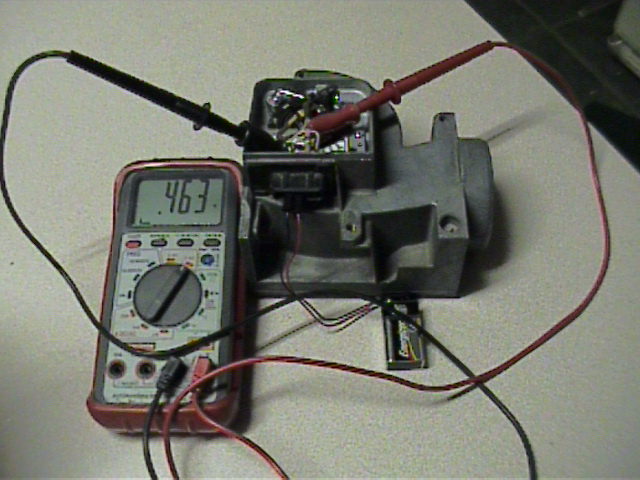
Connect the 9 VDC battery negative lead to Terminal 4 on the AFM connector and the positive lead to Terminal 3.
Connect the voltmeter negative lead to the ground terminal (2) on the inside of the AFM and the positive lead to the sensor output voltage terminal (4). You should obtain a small voltage indication on the voltmeter. Using a new 9 volt battery which was reading 9.41 VDC prior to the test, I obtained slightly less than 0.5 VDC (.463 volts to be exact).
Slowly open the AFM barn door and observe the voltage. The voltage indication should increase steadily as the barn door is opened with no drops or large fluctuations in voltage. With the barn door full open the voltmeter should read slightly less than input voltage. In my case with the 9.41 VDC input voltage, I obtained an full open output voltage of 8.45 VDC.
If any voltage drops or large fluctuations in voltage are noted, there are probably dead spots in the potentiometer conducting strip. This can sometimes be corrected by changing the position of the wiper arm. That will be discussed in the next section.
AFM Cleaning and Repair
Sometimes erratic operation of the AFM can be caused by dirty contacts, dirty conducting strip, or due to grooves worn in the AFM potentiometer conducting strip. This section covers cleaning the AFM and changing the position of the AFM wiper to correct erratic operation.
With the AFM cover removed (see preceding sections), clean the AFM potentiometer conducting strip using a pencil eraser. Work carefully and don't be to aggressive when using the eraser.
Clean the contacts on the bottom of the wiper arm (see picture below) using emery cloth or fine grit sandpaper (400 grit). The best way to do this is to disassemble the AFM enough to remove the wiper arm. If you don't feel comfortable disassembling the AFM, you can clean the wiper arm in place. However, you need to insert a sheet of paper between the wiper arm and the conducting strip first. Then clean the contacts by inserting the sandpaper or emery cloth between the paper and the contacts on the bottom side of the wiper arm. The paper serves to protect the conducting strip while cleaning the wiper arm contacts.
Now that you've cleaned the AFM, it's a good idea to test it again to see if the cleaning has corrected the problem with erratic operation. If it does not correct the problem, and it's obvious that there are deep grooves in the potentiometer conducting strip, adjust the wiper arm position as described in the following step.
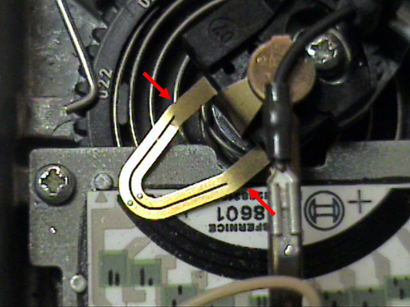
Place a piece of paper between the wiper arm and the potentiometer conducting strip. Change the position of the wiper arm by pushing down on both sides of the back part of the wiper arm (see arrows in picture below) to bend the arm slightly. This effectively shortens the arm such that the contacts on the bottom side of the arm will ride on a different (ungrooved) part of the conducting strip.
Test the AFM as described in previous sections to determine if erratic operation is corrected. If not, the AFM should be replaced.