Fuel level indication problems are generally caused by a problem with the gauge or the sending unit. Our discussion here will focus on isolating the cause of fuel level indicating problems and what needs to be done to fix the problem.
Checking for Proper Gauge Operation
Tools
Mulitmeter
Test Leads
Variable Potentiometer
Sender Resistance vs. Indicated Level
Model Year 1977-1985
Level
Resistance (Ohms)
RESERVE
71.6
1/4
58.7
1/2
34.5
3/4
15.3
FULL (1/1)
3.2
Model Year 1985.5-1995
Level
Resistance (Ohms)
RESERVE
63.2
1/4
42.2
1/2
21.2
3/4
8.6
FULL (1/1)
2.8
Procedure
Remove the carpet from the rear hatch area.
Remove the fuel sender cover. The cover will likely be covered with an insulation pad.
Disconnect the electrical connector from the top of the fuel level sender.
Using the Multimeter and variable potentiometer, set the potentiometer to one of the resistances in the appropriate table for your car.
Connect the potentiometer between Terminals 1 and 3 on the connector. On some cars, Terminal 1 may be labeled "G" and Terminal 3 may be labeled "31" or "T". Make sure that no wires touch a point on the body or fuel tank where they could become grounded.
Turn the ignition to the "ON" position.
Check the indication of the fuel level gauge. The level should indicate approximately the level from the table for the installed resistance..
Turn the ignition to the "OFF" position.
Remove the installed resistance.
Repeat steps 4 through 8 for several resistances across the full range of indication.
Results
If the indications on the fuel level gauge do not agree with those list above, the wiring from the sender to the gauge or the gauge itself is the problem.
If you suspect that there is a problem with the gauge portion of the circuit, first try cleaning the fuel sender grounds. On early 944s (pre-1985.5), the fuel sender grounding point is in the rear hatch area near the left rear light. On late model 944s, the fuel level sender grounding point is on the inside of the firewall on the driver's side of the vehicle (LHD).
You may also try cleaning the electrical connections at the gauge. On newer model cars with instrument clusters, remove the gauge package (ELECT-07) and clean the ribbon connectors on the back of the gauge package with a pencil eraser. On early model cars, remove the gauges using ELECT-06. Clean the contacts for the fuel level gauge and replace the instrument cluster.
If the original test results indicated a problem with the gauge or gauge wiring and the problems persist after cleaning the grounding points and gauge connections, you may want to send the fuel pressure gauge (early cars) or the gauge cluster (later cars) to an authorized repair facility to be checked. I recommend sending the gauges to North Hollywood Speedometer or you can contact VDO to find an authorized repair facility near you.
North Hollywood Speedometer
6111 Lankershim Blvd.
North Hollywood, CA 91606
818-761-5136 http://www.nhspeedometer.com
Siemens VDO Automotive
188 Brooke Rd.
Winchester, VA 22603
540-665-0110
At one time, you could send gauges directly to VDO for repair. Apparently, you now have to go through one of their authorized repair facilities (i.e. NHS is an authorized repair facility).
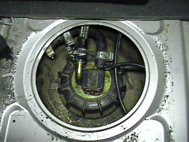
Fuel Level Sender
If results from the test of the fuel level gauge indicate that the gauge is working properly, the cause of the problem is most likely the fuel level sender. Quite often the fuel level sender can become gummed up and a good cleaning may correct the problem.
Start by removing the fuel level sender from the tank. To do this you'll need to disconnect the electrical connector for the sending unit.
Next, disconnect the two fuel lines on top of tank.
On 1985.5 and newer cars, turn the black plastic locking ring counter-clockwise to remove.
On pre-1985.5 cars, remove the five cheesehead screws that hold the sender to the top of the fuel tank.
Lift the fuel sending unit out of the top of the fuel tank.
Thoroughly clean the sender float and slide mechanism using a good engine de-greaser or carburetor and choke cleaner and a brush.
Connect an ohmmeter between terminals 1 and 3 on the sender.
With the float all the way down, the resistance should read approximately RESERVE resistance (see table above for specific resistance for your model year).
Slowly move the float up while watching the resistance reading. As you move the float up, the resistance should slowly decrease to approximately 3 ohms with the float all the way up.
The decrease in resistance should be fairly linear and smooth. If you notice any erratic changes in resistance, then the sender is bad or needs additional cleaning.
If satisfactory resistance readings can not be obtained, the sender should be replaced.